Fire Protection Tank and Pump Room – Villa Rica
Buried hydraulic structure with retaining walls and a high water table
Key Highlights
- 2.50 m concrete walls modeled as fixed at the base and pinned at the top (propped cantilever)
- Water table at 0.80 m depth: hydrostatic pressure included in the design of the walls and slab
- Crack control for severe exposure (z ≤ 17 500 kg/cm, NSR-10 §C.10.6.4)
- Mixed foundation system: isolated footings + a mat that ties all the walls together
- One-way ribbed cover slab with a 5.84 m clear span
Technical Specifications
Context
Storage tank and pump room pit for the fire protection system of an industrial warehouse inside a free trade zone in Villa Rica, Cauca. It is a single-level buried structure with perimeter concrete walls that resist earth pressure, surcharge and hydrostatic pressure, since the geotechnical study reported the water table at only 0.80 m below grade. It sits on site class D (Aa = 0.25, Av = 0.20).
Role
Support role in the structural design. I developed the ETABS modeling, the seismic analysis, the element and foundation design and the calculation report, and supported the production of drawings, under the review and signature of the engineer of record.
Process
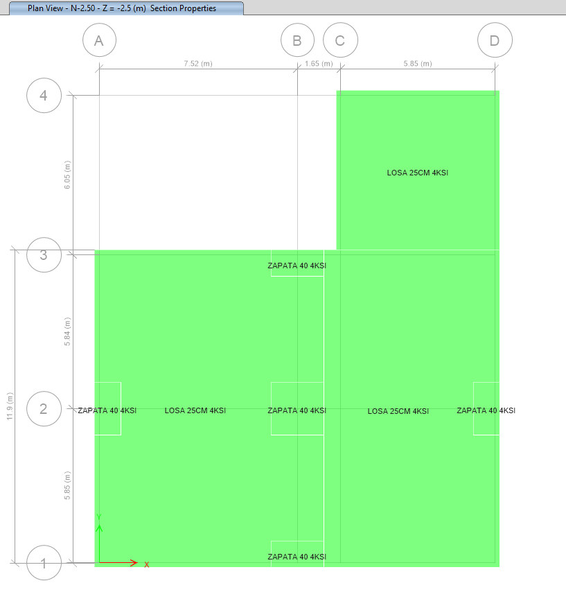
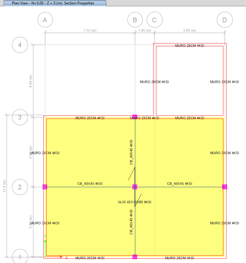
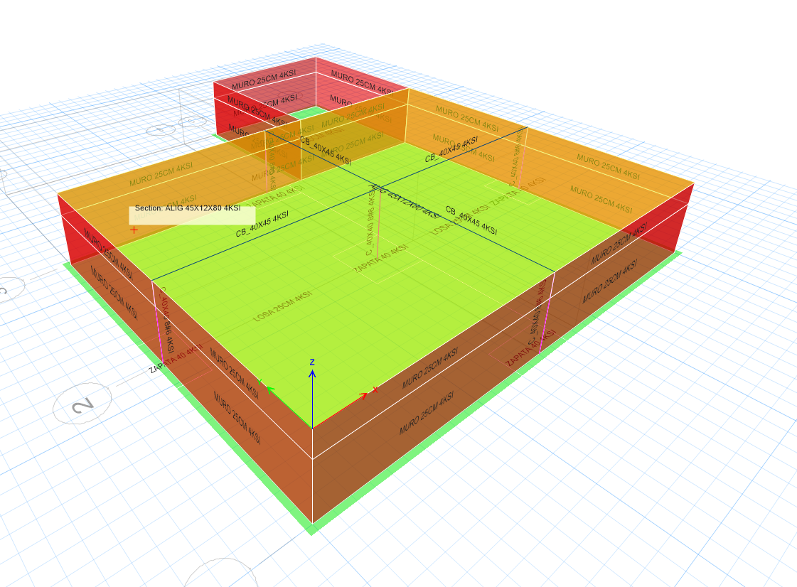
- ETABS model of the tank–pit–slab assembly, with a separate model for the foundation
- Calculation of lateral pressures (at-rest earth pressure K = 0.569, 250 kg/m² surcharge and hydrostatic pressure from the water table)
- Design of the walls as fixed–pinned members, numerically integrating the reactions and the compatibility moments
- Flexure, shear and crack-control checks for severe exposure, with one or two layers of reinforcement depending on the thickness
- Design of the ribbed cover slab (T-beam) with a total depth of 450 mm and a span of 5.84 m
- Integration of isolated footings and a mat foundation to resist the pressures from all the walls
Results
- Walls, cover slab and foundation verified for flexure, shear and cracking under severe exposure
- Soil pressures below the allowable bearing capacity of 11.7 t/m² at −2.5 m
- 47-page calculation report, with custom calculation templates for the walls and the tank pressure
Lessons Learned
In hydraulic structures, durability governs rather than strength. Crack control and the water table defined the reinforcement more than the ultimate moments, and modeling the wall with its actual support condition (pinned at the cover slab) significantly changed the moment distribution compared with a simple cantilever.
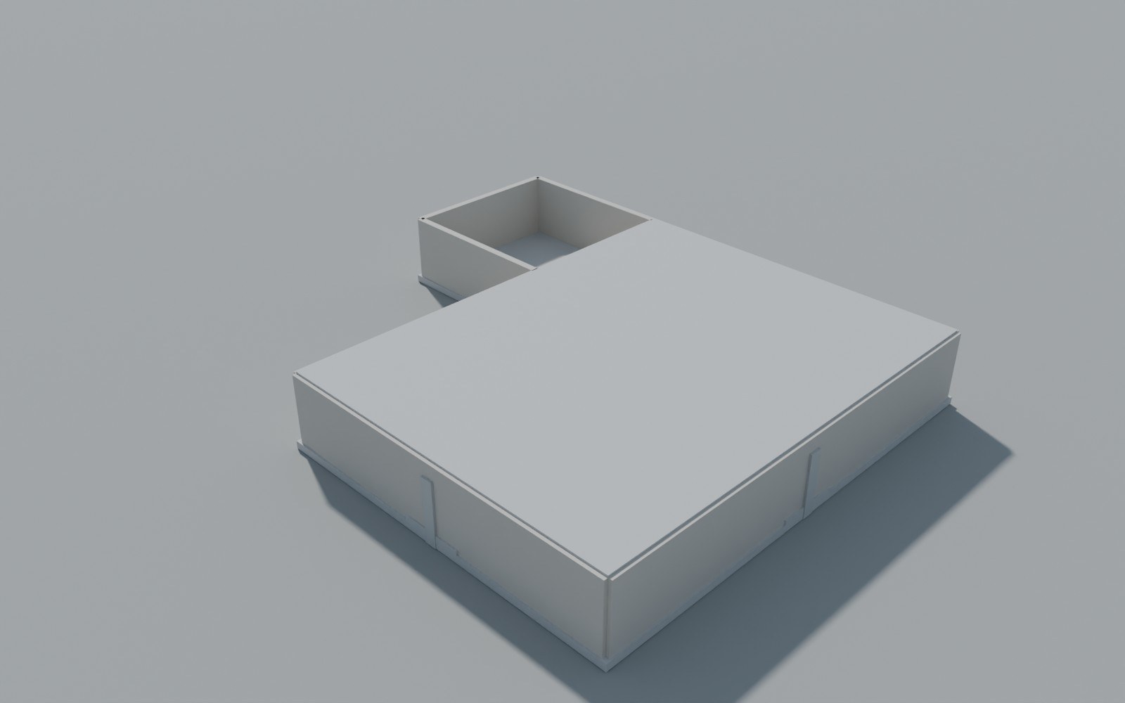
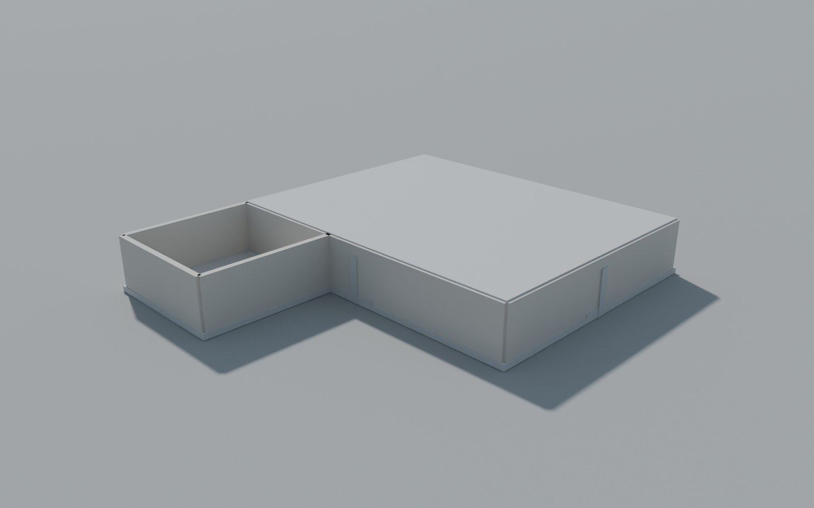
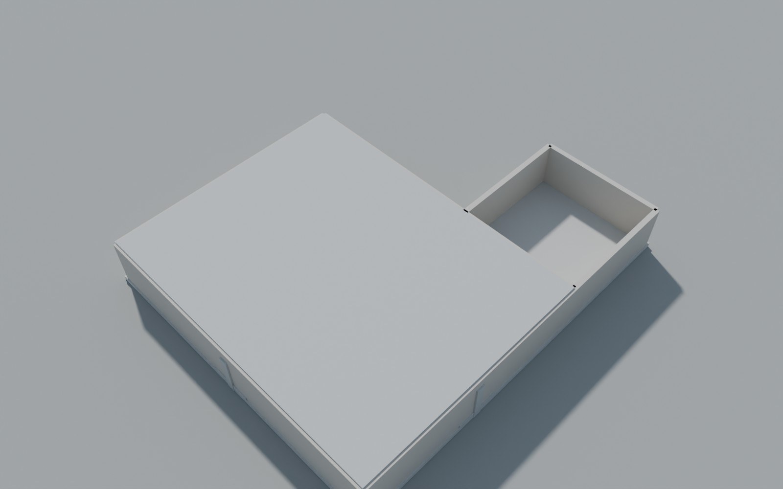
3D Model / Renders (3)
ETABS Analysis (3)